Power factor. Again. I'm sorry.

Regular readers will know that the world currently teems with "power saving" devices, which are alleged to use Power-Factor Correction to save you money on your electricity bill.

These things are absolutely excellent, except for four minor flaws.

One, little plug-in PFC gadgets don't actually correct power factor at all, two, little plug-in PFC gadgets don't actually correct power factor at all, three, domestic electricity customers aren't billed by power factor anyway, and four, domestic electricity customers aren't billed by power factor anyway.

I realise that, technically speaking, that's only two flaws, but I thought they were such big ones they were worth mentioning twice.

At the other end of the commercial spectrum from the BS plug-in power savers, there are big industrial units designed to correct the atrocious power factor of certain particularly serious offenders, like really big electric motors, or really large numbers of smaller motors. Usually these sorts of correction setups are just capacitor and/or inductor banks carefully matched to the load; sometimes they're "smart" devices that adjust themselves to correct varying power factor, which is what you'll get if, for instance, you've got a factory full of big motors that keep changing speed and load.

This sort of PFC, and similarly large-scale PFC that's implemented by the actual power companies (typically in the form of big capacitor banks at substations and other distribution transformers), is entirely genuine, quite useful, and very expensive. But if you're billed by power factor, or if you're a power company that wants to minimise the mass of metal in your whole distribution network, PFC is essential.

In between the little rip-off plastic home-user things and the vast custom capacitor banks in power stations are, as you'd expect, PFC devices for medium-load applications. Yesterday I corresponded briefly with someone who's trying to sell such devices.

Regular readers won't find anything very new and exciting in this correspondence, and I wouldn't blame any reader for only lightly scanning at least the first giant block of quoted text. I'm posting this mainly so that Google searchers will be able to find a little more info about this field in general, and this product in particular.

(Also, I've suffered for my art, so now it's your turn.)

From: Tim Otto <tim@powerceosales.com>
To: dan@dansdata.com
Subject: Active and dynamic PFC.
Date: Wed, 3 Mar 2010 20:15:51 -0600

Dan, I was reading your article and wanted to share with you our new technology. I agree with you on a residential level that the current PFC units don't save you money ,but when you take PFC and only put it in the circuit and remove it there is a savings. I am reaching out to all the blogger on the net and am asking them just to consider that what I'm saying is real. We have seen savings and when the product which just went to mass production get here I am reaching out to all bloggers on all continents to get a unit in their hands. I don't want to sell it to you. It will sell its self when you see it work. On the business side the meters do read different here in the states and the savings is much greater. Please take time to read the PDF study and when we hit your continent we can get one installed for your testing.
Why is power factor correction an important part of reducing co2 emissions and is there any new technology available to ad to the global effort? Yes, let me explain where this large void is occurring. Large industrial power users (demand side) have been using power factor correction (pfc) for years on large motor driven equipment because its too costly paying the power providers for this wasted reactive energy (poor p.f.). There is a demand (penalty) charge on their monthly bill including all commercial users. Several companies build PFC units by incorporating capacitors in various amounts to match the loads of running motor(s) to offset this penalty. These units are large and tailored to do a cost saving job for this industry. The user and power provider both see a power usage benefit.

Home and commercial users share the burden of poor power factor and extra power must be provided to offset this waste. Air conditioning, furnace blowers, refrigerators, freezers, washers, dryers, fans, garbage disposals, dishwashers, lighting with ballast or transformers, pool pumps etc all ad to the burden. Whitby Hydro Energy Services of Canada did a series of test in 2005 by taking a group of homes and using pfc devices with a set amount of capacitance. Their conclusion: ‘The result of the pilot indicated that the addition of capacitance indicate that installation of the units on mass will reduce the generation requirements through the province and we recommend that the findings of this pilot be shared with the government officials as a viable means to help address the supply and transmission issues within the province”. The full 15 page PDF report is attached.

[The above quote isn't quite what the report actually says, but it's basically correct. Yes, the report does actually use the term "on mass". Hey, give 'em a break - they're in Ontario. Nobody speaks French there.]

No doubt Whitby Hydro could save on power generation so why not mandate to use pfc units on homes and business and save a new power plant from being constructed? To make this possible a pfc unit would have to turn on and off when motors and ballast/transformer type lighting were operational and make constant capacitance adjustments to correct the different loads and voltage fluctuation drops caused by peek demands. A good pf correction is .95-.96 and going higher can cause frequency modulation problems. Present pfc units are fixed or variable and cannot perform the computerized functions that would be required. This is where Power-CEOtm (Computerized Energy Optimizer) fills this gap. Our patented (USA and most countries) power factor correction units is the first to incorporate the proper technology for global usage. Here is what the patent-holder has to say: “We are confident that our patented “Power-Factor-Correction” technology is light years ahead of the other PFC systems. By and large, most PFC systems are either “Static” (designed for a specific amount) or a hybrid of “Limited Automatic,” designed around several variables and are thus referred to as automatic. However, our power-factor-correction technology is fully and completely Dynamic/Automatic in that it will turn on precisely the amount of correction required in order to attain a PF of .95 and not only that, in the event an additional load turns on or is introduced into the system requiring additional compensation, our Smart System will automatically and instantly adjust to the new required setting. When any load which was requiring the compensation either turns off/on or changes its setting (for example, motors with varying loads), our PFC system will readjust and continue to readjust as needed in order to provide as near to a PF setting of .95 continuously as is feasible.
The current US President, as well as our previous President both stated when talking about the Kyoto Protocol and Copenhagen Meeting on the Environment, that they believe technology will be developed which will help us reach ascertainable goals without significantly hampering commerce. As you will see, Power-CEO™ is one of those technologies.”

Midwest Research Institute, a Government funded institute, has been involved since
2001 helping with technology issues until Power-CEO was completely viable and ready to market, and UL approval has been met. Plamen Doynov the senior engineer from MRI has this to say: I am intrinsically familiar with the technology. I was involved in the development of the original analog implementation during a contract with McDaniel brothers. Consecutively, we performed performance testing of the digital implementation of the technology. A copy of the performance report can be provided. In the report one can see that the testing of the technology confirms that it performs very well as a dynamic power factor correction unit. I am not writing this email as a representative of MRI. As an independent, not-for-profit, contract research institute, MRI has a strict policy not to endorse products, technologies, or cervices. Given an opportunity, MRI has the capacity to test and evaluate very broad technologies and systems. Should you need assistance from MRI in testing, evaluation, or further enhancements of the Power-CEO, I can facilitate the arrangements. Plamen Doynov

Power-CEO is ready for production and can comply to any world specification. Power-CEO is ready to meet the demands of lowering power consumption.

[Attached was a PDF report from Whitby Hydro Energy Services, "Power Factor Correction at the Residential Level - Pilot Project", which is available from here, and quickly viewable in-browser here.]

My reply:

I agree with you on a residential level that the current PFC units don't save you money ,but when you take PFC and only put it in the circuit and remove it there is a savings.

I'm not sure what you mean by that. By definition, there's only a saving for people who are billed by power factor, or for people who are in the business of generating and transmitting electricity.

On the business side the meters do read different here in the states and the savings is much greater.

I'm also not sure what you mean by this :-).

There is a demand (penalty) charge on their monthly bill including all commercial users.

Really? How's a "commercial user" defined, then?

The local corner store here is unquestionably a commercial electricity user. I don't think they're billed by power factor.

Home and commercial users share the burden of poor power factor

Yes, in the indirect sense that power in general is made more expensive when electricity utilities have to cope with higher kVA than kW. But no home user will achieve any direct savings by improving their own power factor.

Whitby Hydro Energy Services of Canada did a series of test in 2005

...in which, according to the PDF you attached, they had to install special meters at the homes in order to see any difference, because of course the standard electricity meters do not measure power factor.

Even if all of the houses connected to the tested transformers were directly billed by power factor, though - so if your power factor is 0.9, you pay 1.11 times as much as someone with a PF of 1.0 - the reported improvements in the two transformers with the PFC added would only reduce consumers' power bills by less than 5% and less than 3%, respectively [I averaged out the five tested months in the PDF report].

There'd have to be a penalty rate far in excess of the actual extra volt-amps used to make it attractive to install a PFC system that cost more than a very small amount.

What does your product actually cost? How large would a customer's current power bill need to be to pay your product off in, let's say, five years, assuming it somehow allows that customer to reduce their power bills by even 5%?

No doubt Whitby Hydro could save on power generation so why not mandate to use pfc units on homes and business

Uh, because people don't want to buy expensive things that won't save them, personally, any money :-)?

I am unconvinced that widely-distributed household PFC installations, as opposed to the PFC systems already being installed in electrical substations, are a cost-effective proposition, even if you make them mandatory and have the taxpayer pay for them.

As a "retail" product for voluntary installation by homeowners, they appear to be a total non-starter.

A good pf correction is .95-.96 and going higher can cause frequency modulation problems.

Wait - so now you're saying that the 99.22% and 97.5% five-month average figures from the Whitby Hydro transformer study (versus 94.7% for an unmodified transformer) are undesirable?

The Power Medix device mentioned from page 11 of the PDF you sent apparently went considerably above 96%, as well. I find the figures there rather questionable, though; uncorrected power factor is way down in the .75 to .80 range at night. If that's the result of a water heater or geothermal heat pump or something, clearly that one something is what the power company should be giving that household a free power-factor corrector for, not the whole house.

If your special patented product carefully keeps the PF close to 0.95 at all times, I don't see that there's much of an improvement to be gained. Even if domestic consumers people start being billed by power factor. Which I doubt will happen any time soon, since it's hard enough to even explain what power factor IS to people, much less get them to re-elect someone who took their money because of it :-).

The current US President, as well as our previous President both stated when talking about the Kyoto Protocol and Copenhagen Meeting on the Environment, that they believe technology will be developed which will help us reach ascertainable goals without significantly hampering commerce.

I wouldn't say that in the press release, if I were you. We both know that few-per-cent improvements in power factor are not at all the sort of thing that heads of state are talking about when they make speeches like that.

Your repeated use of the word "patented" as if patents are only awarded for worthwhile inventions seems to me to be another unfortunate tactic.

Power-CEO is ready to meet the demands of lowering power consumption.

Another claim I think you should stop making.

A poor power factor, BY DEFINITION, does not mean that ANY more power is actually being consumed, except for the amount lost to resistance from higher current flows. That's significant for a power company, but vanishingly small for a home user. And even for most industrial users; they only care about PFC if they're billed by power factor.

In reply to this, all Tim sent me was:

Hears a link ,see what the power company has to say.
Also has anybody done a test where every item was corrected in a structure ?

http://www.psnh.com/Energy/ReduceBill_Business/PowerFactor.asp

My reply:

Hears a link ,see what the power company has to say.

That page says:

How correcting power factor can save money
The PSNH demand charge is based upon kva demand for LG customers and upon 80 percent of the kva demand for GV (Commercial and Industrial) customers who have a power factor of less than 80 percent. Power factor correction may offer a savings opportunity for some customers.

"LG" is one of PSNH's "Large Business" tariffs, for "demands in excess of 1,000 KW" (PDF; domestic power consumption is more like 1 to 2 kilowatts, depending on what sort of "average home" you're looking at).

Small businesses are only even possibly affected by these issues if they actually have a low power factor, which outfits that aren't running lots of low-power-factor gear - typically, large motors without PFC capacitors already on them - will not have.

Stores with a huge bank of fluorescent lights may have a lousy enough power factor to be interested by this, but I think modern electronic ballasts have largely solved that problem. The same goes for computers; PCs used to have a pretty consistent 0.7 to 0.8 power factor, which could add up for a whole office full of them, but nowadays most PC PSUs have PFC built in, for exactly this reason.

Also has anybody done a test where every item was corrected in a structure ?

Only if the power factor is actually low enough to make the cost of correction attractive, which in normal domestic situations it is not.

Homes that draw a lot of power often draw it for things like electrical heating, which is almost entirely a simple resistive load with a power factor of 1. And in any case, to say it one more time, no homeowner is going to be interested in PFC if they're not billed by power factor. I am not aware of any nation in which private homes are billed by power factor. You'd think that there'd be some huge housing developments that were billed that way, but if there are, I haven't discovered any.

Since you did not choose to answer my questions, I can only presume that you have no answers for them. Sorry, but I cannot take further time to correspond with you if you're not actually offering anything new.


I don't know what the deal is with people like Tim. He doesn't seem to be deliberately running a scam, but he also keeps saying that products like his are for some reason going to become popular for home and small commercial electricity users. Those users don't actually have any reason to install a power-factor corrector unless they feel philanthropic toward the power company.

And if you do want to do the power company, or the planet, a favour by taking some load off the electricity grid, a much better idea for domestic power consumers is to look into a grid-connected solar system, which can genuinely reduce your power bill.

In many countries, new home solar-power installations are heavily subsidised by the government, for either purchase price, feed-in tariffs, or both. You may also be able to get a subsidy if you install a solar water heater, which is a simpler and less expensive investment than a photovoltaic solar electricity system.

Even if you can get a power-factor corrector for free, though, there's absolutely no point installing it unless you are for some reason using quite a lot of power, with a lousy power factor. Even houses that use a lot of electricity - electric heating in cold climates, big air-conditioners in hot countries, a giant bank of metal-halide lamps in the garage for some reason - don't necessarily have a lousy enough power factor for any add-on PFC to be necessary.

Don't buy "BTY" batteries!

I needed six rechargeable AA cells for an old Hanimex potato-masher flash, which I bought cheap the other day to do some Strobist experimenting. I've only been buying low self-discharge ("LSD"!) NiMH cells for a while now, but I don't have six identical AA LSD cells spare at the moment, and I didn't want to drop the substantial extra amount of money to buy six more LSD cells for a flash that I'm not necessarily even going to use much.

So I hit eBay, looking for the finest, cheapest NiMH AAs in the world. And I won an auction for twelve allegedly-2500mAh "BTY"-branded NiMH AAs, for 5.5 UK pounds (about $US8.30 or $AU9.30, as I write this).

Fake BTY NiMH AA cells

That one on the right didn't explode; I ripped it apart to see what, if anything, was inside. 'Cos it sure wasn't a 2500mAh NiMH cell.

I didn't, to be fair, actually expect these AAs to really have a capacity of 2500 milliamp-hours. Capacity inflation is rampant in the rechargeable-battery market. Even the big brands often seem to pump up the capacity numbers a bit, and it's perfectly normal for an off-brand "2500mAh" cell to have a real capacity of only 1500mAh or so.

That was fine with me, though, especially for less than ten bucks delivered.

(I think you even get the "off-brand PC power supply" situation, in which some dealers sell a range of cells specified from 2000mAh all the way to a truly audacious 3000mAh, but all of them actually have the same 1500mAh-ish cells inside the wrapper. DealExtreme, for instance, sell "2000mAh", "2300mAh", "2500mAh", "2800mAh" and, yes, "3000mAh" "Maxuss"-branded AAs, with the allegedly-higher-capacity ones priced accordingly. The user reviews suggest to me that you might as well just buy the cheapest ones. If there's a difference besides price and the printing on the label, it doesn't appear to be a large one.)

These BTY cells were much worse than I expected, though. I knew something was up as soon as I opened the package; the BTY cells are way too light. They weigh about 18 grams each, versus 29 grams for an old Sanyo 2500mAh cell, and 30 grams for a Sanyo Eneloop LSD AA. They're substantially lighter than the old worn-out 1650mAh off-brand cells still mouldering in the bottom of my Battery Drawer.

My Maha C-808M charger (yours, Australian shoppers, for $AU183.15 delivered from Servaas Products) didn't like the look of the BTYs, either. It did charge them, but flashed its "battery fault" error at the end, possibly because the charge cycle was over so quickly.

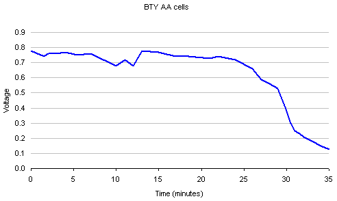
To their credit, the BTYs did run my flash. But not for very long. When I charged them again and hooked one up to a 0.9-ohm resistance (a horrifying load for an alkaline cell, no big deal for a rechargeable), I got a useful run time...

BTY AA NiMH discharge graph

...of about 25 minutes, for a total capacity of maybe 350 milliamp-hours, with a following wind. (The terminal voltage also dropped to less than 0.8V immediately, even into this modest-for-a-NiMH-cell load.)

It was at this point that I disembowelled one of the BTYs. I was half-expecting to find a fractional-AA or AAA, or something, in there, but the casing was actually full of the normal Swiss-roll sandwich of metallic electrode and noxious-electrolyte-soaked separator. I'm not sure whether the BTYs are actually nickel-metal-hydride or mere nickel-cadmium cells; I don't think you can really tell just by looking. They certainly only have the capacity of the ultra-cheap NiCds you get in bargain-store solar garden lights, though.

(There are honest dealers that sell these sorts of cells, by the way. Here's an eBay search that finds one current dealer's particular description of them. I have no experience of that particular dealer, but they'd have to be pretty perverse to misdescribe low-capacity NiCds. Note that you still don't necessarily want these cells, even if you only need low capacity, because NiCds contain highly poisonous cadmium, and remain a serious disposal problem.)

Aaaanyway, I filed a PayPal dispute over this, and anticipated a long and painful experience. So when I got an e-mail from PayPal the next day saying the dispute had been closed, I of course assumed that someone at eBay had decided I was ineligible for a refund because it had been three months since the dispute was filed on the 35th of Octember and I still hadn't had the batteries X-rayed by a fully licensed Federal Hat Inspector while I whistled Dixie and a five-legged elephant painted my naked body with the full ceremonial vestments of the Ecumenical Patriarch of Constantinople.

But the dispute was actually closed because the seller had instantly knuckled under, and given me a full refund.

If there's one thing I've learned from reading The Consumerist, it's that whenever you complain about some crazy fee and they instantly reduce or waive it, you're always looking at a scam. (Well, almost always.)

And lo, searching for other people's experiences of "BTY" batteries turned up a number of reports astonishingly similar to, though blessedly less long-winded than, my own.

This guy tested a range of cells and found BTYs ranked equal worst. There are people complaining about them on DealExtreme (or, at least, giving them one-star ratings). Heck, there's even a Guide post on eBay itself that warns about them.

So, on balance, I'm not sure that I actually deserved to get my money back.

There are plenty of eBay dealers, including the one I bought from, who are still selling "BTY" cells. Some of them have taken the advanced camouflage measure of calling the cells "BT" instead of "BTY", but my advanced h4XX0ring skillz can still find them.)

Don't buy those batteries.

Oh, and how did I solve my flash-powering problem? Well, the awful BTY batteries do actually power it for a little while; for longer run time, I just yanked the six-cell NiCd pack from a giant robot bug I'm not currently using and hacked up a lead to connect it to the flash's external-power-input pins.

Ridiculous camera rig

So now I can make a camera rig that looks even stupider than this!

Maxwell's equations are what the Freemasons WANT you to believe

A reader writes:

After an idle evening reading the comments section (I know) on the blog of the BBC's US correspondent, Mark Mardell, I came across this ... interesting perspective.

258. At 04:12am on 09 Feb 2010, KingLeeRoySandersJr wrote:
I can answer why electrical power in most of the USA is above ground. The reason is simply in the USA power lines are carrying much more voltage and current than in Great Britain for the most part and travel greater distances. Electricity doesn't simply flow through the wire but on the outside of a wire. The circumference of the wire carries the power if it were underground much of it would be lost in the ground.

Now here is something you don't know. Power companies use different transformers under different conditions. Ever plug in a device and the wire gets warm but other times it doesn't? That happens because when there is a great power demand the power companies try to fool the public that there is adequate power by simply supplying the voltage and the device works.

But this is not what they are telling you. The voltage is there but not the current the device demands in it's productive use of wattage to function. It can't obtain it on the gauge of wire it is designed for and the wire gets hot, homes burn down, lives and possession are lost! Simply because inadequate power is produced. Voltage ratings exist but only because current is decreased. This creates the illusion of adequate electrical power.

[...]

I can't identify a single thing in that comment that appears to be true. Am I wrong?

Jonathan

Yes, "KingLeeRoySandersJr" does appear to have a very independent mind. Perhaps he read something about power factor somewhere, and then took further guidance from disembodied voices.

But no, he's not wrong in everything he says. I guess, for instance, that if you were to run un-insulated power lines underground, you probably would lose a lot of power. For analogous reasons, jet fighters without windscreens do not work very well and cars without wheels have disappointing top speeds. Humanity waits patiently for the genius who can unravel these mysteries.

(Fortunately, the extra weight of insulation ceases to be a problem when you no longer have to hang your wires from poles. A lot of people find it surprising that overhead power lines are almost always un-insulated; this often seems to be because they don't know the difference between insulation and shielding. My learned colleagues at Harmonic Energy Products had this problem many years ago, and the confusion also cropped up in connection with this gloriously stupid audiophile power cable.)

The first thing KingLeeRoySandersJr says, about current flowing through "the circumference of the wire", is also not complete nonsense. He's talking, assuming he's got some connection with consensus reality, about the "skin effect", in which the higher the frequency of the AC you're trying to push through a wire, the shallower will be the depth into the wire in which significant current flow occurs. This has to do with eddy currents, which cancel each other out in the middle of the wire but increase current flow on the surface.

Some huge power-transmission lines are DC, which has an infinite skin depth, and some transmission lines for exotic applications - like particle accelerators - run at high frequencies. But changing the frequency of AC is as difficult as changing its voltage is easy, so the vast majority of high-voltage long-distance lines run at the same 50 or 60Hz as the rest of the grid. "Skin depth" - the depth at which current density is one-on-e, or about 37%, of the current density at the surface - at 50Hz is around 9.3mm for pure copper and almost 12mm for pure aluminium, unless the calculations I just did based on Wikipedia's tables of permeability and resistivity are based on subtly vandalised numbers. At 60Hz the depth drops a little, to around 8.5 and 10.9mm, respectively. If you're for some reason shifting 1kHz AC, your skin depth falls to 2.1 and 2.7mm, respectively.

Audiophile nitwits sometimes bang on about skin effect, and pay big bucks for cables with zillions of tiny separately-insulated conductors, maybe woven like Litz wire and maybe just floating around as a cloud, in order to defeat it. The theory is that skin effect increases cable resistance for high frequencies, so you lose treble - or "musicality", or "coherence", or whatever it is they've made up now - if your cables are too fat.

But even if your golden ears have the mystic ability to perceive 40kHz sound, an octave higher than the usual rule-of-thumb 20kHz upper bound for human hearing and higher still than the maybe-14kHz that's the highest most young-ish adults can perceive, skin depth in copper wire will still be around a third of a millimetre at that frequency. This gives plenty of copper to conduct your line-level or speaker-level signals, at all audio frequencies, in just about any cheap cable you care to name, and a resistance difference for 40kHz versus 10Hz of three-fifths of bugger all (a technical term), even if you hook everything up using the now-nearly-proverbial coat-hangers.

(God help me, I just searched for "skin effect" and "digital interconnect" and yes, right there on the first results page are people selling a carbon-fibre RCA cable for digital data that's supposed to be better because, among numerous other brain-hurting explanations, it ain't got no skin effect. It can be yours for a mere $US225!)

Clearly, at normal mains frequencies you need a pretty darn thick conductor before skin effect makes much difference. Big power-transmission cables are pretty darn thick conductors, though, so yes, it affects them. Most aerial power cabling is aluminium (which has higher resistance per unit area than copper, but lower resistance by weight, which is very important for cables strung from towers), but I think it's quite common for those cables to have thin steel wires in the middle to improve their strength. Steel is a pretty terrible power-transmission material, having a skin depth of less than a millimetre at mains frequencies (and yet mild-steel coat-hanger wire keeps passing those blinded audio tests!), but it doesn't matter when skin effect confines most of the current to the outer, aluminium portion of heavy power-transmission cable.

The allegedly-wireless allegedly-RCA "Airnegy" alleged charger

A reader writes:

You're probably getting about a million questions on this gizmo from CES, but do you think the RCA Airnegy WiFi charger is anywhere near remotely practical?

Airnegy charger

They claim it will "harvest" energy from 2.4GHz devices, like wireless phones and WiFi devices. They say it can charge a cell phone from 30% to full in 90 minutes on the CES floor, which is confusing because of all the wireless devices on the CES floor and the fact that many cell phones report full early to make their batteries look better. Since a Wi-Fi device operates at 100mW and that shrinks with the inverse-square law, wouldn't any Wi-Fi power be trivial?

Would this only be practical if you had a lot of overlapping Wi-Fi hotspots and/or a huge charger, or am I missing something? They're even claiming they can integrate this into batteries in the future.

If this is a scam or borderline useless, why is RCA promoting it? I could understand this kind of trash from a fly-by-night operation like all the fuel-pill pages, but I would think RCA would want to keep some of its reputation.

Tim

Yes, I think this has to be some sort of hoax. I ain't no RF physicist, but I don't think the numbers add up at all.

(I am, unsurprisingly, not alone.)

The output of the very small charger for my very low-powered mobile phone (a Motorola F3) is specified as 6.4V @ 200mA, which is 1.28 watts. The output of a standard Wi-Fi access point is, as you say, limited by the spec to 100 milliwatts. And, again as you say, the laws o' physics dictate that even if this thing contains a beautifully-engineered rectenna that hoovers up 90% of the 2.4GHz-ish RF energy that impinges upon it, it'll still collect far, far too little power to do anything very useful. For the same reason, it is difficult for a device the size of a canoe to harvest much energy from the wake of a passing ocean liner.

It's actually not quite as bad as you might think from a pure inverse-square law calculation, because the "impossible antennas" used in normal access points have a sort of inverse-hourglass-shaped radiation pattern, concentrating output around the antenna at the expense of output above and below it. If you're lined up with the radiation pattern of one of the larger "omnidirectional" Wi-Fi antennas, you could easily be getting three or four times as much power as you'd get if it were a real omnidirectional antenna.

But unless the Airnegy is squished right up next to the antenna so it covers, and near-totally absorbs, some relatively large fraction of the entire radiation pattern (and, of course, thereby makes devices in its "shadow" unable to see the AP any more...), then the energy it'll receive even from several out-of-specification half-watt Wi-Fi adapters will be extremely low. Never mind charging a phone - you wouldn't even be able to light an LED.

(A crystal radio can run on the RF energy from its own antenna, but that's in the microwatt range, at best.)

I suppose a device with some sort of broadband fractal antenna in it, that can suck up everything from 50Hz mains hum to high-gigahertz radar beams, might be more practical. But the Airnegy is said to be 2.4GHz-only.

Oh, and there doesn't seem to be any mention of this product on the RCA site. And although the Airnegy CES stand looks professional, the products themselves look like quick mock-ups to me. Look at this battery, for instance. It looks as if they put a construction-paper wrapper around a standard battery.

(I presume someone's paid to have the stand there, too, unless CES was having trouble filling the floor and let in hoaxers for free, like the funny fake ads that fill holes in newspaper classifieds.)

Note also that RCA is now, I think, one of those "zombie brands" that has been reduced to nothing but a logo that's slapped on random Chinese flea-market gadgets. So even if it actually is a "real RCA product", that doesn't mean much any more.

This also isn't a new idea. Here's a piece about a "prototype Nokia phone" that's supposed to somehow harvest five milliwatts from incident RF.

Can any readers who've got some of that fancy book-learnin' about that thar electrickery help me out, here?

(Somebody on that Boing Boing post busted out the Friis transmission equation.)

Has anything at all like this thing ever actually been made to work?

(And no, inductive chargers don't count!)

A very bright bad example

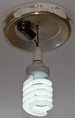
I used to have a really big light bulb hanging in the junk-storage/photo-studio/emergency-guest-accommodation room.

Big bare bulb

I wrote about it here, very early in the life of this blog.

Unfortunately, that 85-watt compact fluorescent lamp, which we came to affectionately call "the skylight", only lasted a couple of years. That might have been because it wasn't very well-made, but I suspect it just didn't like being turned on and off so often. I wasn't in and out of the junk room a dozen times every day, but CFLs only have so many on/off cycles in them.

After the eighty-five-watter died, I sighed and put a standard boring "100W-equivalent" bulb in the dangly hacked-together socket I'd used for the big lamp. And there that boring bulb stayed, for about another year.

But then, the other day, I noticed that this eBay seller had some new-old-stock Y-adapters, for Australian light-bulb sockets.

(In the USA, the most common light-bulb socket is the "E27", a 27mm Edison screw. Here in Australia, though, the large majority of our light bulbs use a 22mm bayonet mount, a.k.a. "BC".)

The eBay seller turned out to have a total of nine double-adapters, some with a switch for one of their branches, some without.

I don't like to miss a chance to go beyond the usual and construct something that'd make a home inspector turn pale and need to sit down for a little while. (The Cable that Should Not Be was the third post on this blog!)

So I bought all of the adapters.

Ten-bulb CFL monstrosity

And now I have this!

Nine double-adapters, ten sockets.

In case you're wondering: No, this is not a good idea. Do not do it.

What you see in that picture is actually my third attempt to get everything working at once. I first tried a couple of "bushier" layouts, but the leverage of greater bulb-weight on the wider branches produced broken or, worse, arcing connections between the adapters. So I reconfigured the motley convocation into this vaguely Christmas-tree-ish shape.

The less bushy configuration puts the bottom bulb only about 204 centimetres (six feet, eight inches) above the floor. And this many stacked bayonet connectors becomes sort of... floppy. So a tall person bumping their head on the bottom bulb might manage to unplug half of the assembly. And I don't trust all of the connections to really be free of slow-overheating-causing extra resistance or tiny arcs. So I wouldn't leave this Photonic Agglomeration Mark I turned on when I left the house.

But, dodgy though this preposterous bricolage of brightness is, it's actually not as dreadful as you might think.

Light-bulb double-adapters were, in the olden days, a way to buy several tickets in that special lottery where the grand prize is burning your house down.

A light-bulb socket should remain safe, you see, even if you run a few hundred watts from it. But there are plenty of ceiling lamps that're blessed with cack-handed amateur wiring, old cables chewed by rats, old connections corroded by possum pee, ancient insecure aluminium wiring, flammable insulation batts installed right across the top of hot areas, or some combination of the above.

If you double-adapt a light-bulb socket that's hanging down from the ceiling on a cable, then you at least shouldn't be able to dangerously increase the temperature of the ceiling above the bulbs. But it's still perfectly possible that you'll overheat some wiring.

The whole point of compact fluorescent bulbs, though, is that they consume a lot less power than incandescents, for a given brightness. A "100-watt equivalent" CFL will probably draw only 18 or 20 watts. So you can double-adapt a whole bunch of CFLs onto one standard socket and run no more risk of disaster - from excess current, anyway - than you would if you'd plugged in only three or four incandescent bulbs.

In my illuminative monstrosity, there's one 23-watt CFL, five 18-watt, one 14-watt and three 10-watt, for a total of a mere 157 watts. You can buy single incandescent bulbs that draw that much - or 200 watts, even - if they've not yet been banned where you live. Those big bulbs will usually work fine in normal ceiling fixtures if they physically fit, and they also often have an extremely long lifespan. That's because they're built for toughness, not efficiency, though, which brings us back to the subject of light-bulb bans.

(Most standard incandescents are now effectively banned here in Australia, but there are specific exceptions for bulbs for which high-efficiency replacements do not yet exist, like the little lamps in fridges and microwaves. So nobody seems to have been terribly inconvenienced. In a few years, immortal LED bulbs ought to have stepped up to fill pretty much every niche that doesn't actually require a lamp that wastes power.)

157 watts of compact-fluorescent light is getting on for twice the power of my old 85-watt single bulb. It ought to add up to an incandescent-equivalent figure of more than 800 watts. So I whipped out the light-meter to see how the new fluorescence excrescence did.

Compact fluorescents don't give their full brightness until they've warmed up, and that can take a minute or three. Some CFLs are really dim when they're at even a comfortable room temperature, and all of them will be very dim if they're very cold (which can be annoying if you want to use them as a porch light in a cold climate, or to illuminate your meat-locker). So I measured the brightness of the new Lamp That Should Not Be at turn-on at the ambient temperature of about 20°C (68°F), and then again ten minutes later. I taped my light-meter's sensor to the wall about 195 centimetres from the middle of the array, looking at it from a bit below, but broadside-on. (A flat array of bulbs like this will, of course, be dimmer if you look at it edge-on.)

At turn-on, the multi-lamp managed a brightness of about 125 lux over there on the wall - already more than twice the usual brightness of domestic indoor lighting. Ten minutes later, it was 344 lux. Left to warm up even longer, it plateaued at 360 lux.

At the front of my photo-tent area (located, since the kitchen table is not available, in the second-most-traditional location for professional Web-site photography, a spare bed), the old 85W CFL managed about 205 lux. The new array manages about 345!

That's still not bright enough for general photographic use. It's more than enough for large-aperture portraiture, but for product shots you'll find yourself needing one-second tripod exposures. It's a really good light level for a workroom, though; bright enough for fine work, without the actinic glare of a 7-Eleven at two in the morning. (Which is exactly the same brightness as a 7-Eleven at ten at night, but always seems a lot brighter.)

At the standard measuring distance of one metre, by the way, the warmed-up ten-bulb Chandelier of Uncertainty manages better than 900 lux - overcast daylight brightness - when measured from a perfect broadside-on location. An edge-on view of the lamps one metre from the middle of the whole array is still about 900 lux, because the lamps at the near side of the array are now rather closer than one metre. Moving back to take that into account drops the brightness to around 700 lux.

The ten bulbs cast a rather pleasant light, too. Because the light comes from so many sources - and the sources themselves are the tubes of CFLs, not the little filaments of clear incandescent bulbs - the light casts the soft shadows that you can normally only get from efficiency-reducing lampshades or indirect lighting. And the random mix of colour temperatures from ten supermarket bulbs might drive pro photographers to distraction (because all shadows will have multiple soft fringes of subtly different colours...), but I think it makes the room look sort of sunset-ish, without actually being very yellow. The only problem is that when I come out of the junk room into the normally-lit house, I can't see where I'm going any more.

Early compact fluorescent lamps were widely hated, for good reason. They were quite expensive, and they gave light that was qualitatively inferior to that from incandescent bulbs. Their mains-frequency ballasts gave them noticeable flicker, which in turn gave people noticeable headaches, and early CFLS also often used the cheap high-efficiency "triphosphor" coatings. Triphosphor gives lots of light per watt - it's still pretty much ubiquitous in the cheap-straight-fluoro-tube market - but it has lousy colour rendering, so people look like corpses and you can't tell your jelly beans apart.

But modern CFLs, even cheap supermarket ones, now have high-frequency ballasts and pretty decent colour rendering. Especially if you combine lots of different lamps into one fitting!

(Current CFLs even have a good power factor now. So my irradiative congerie shouldn't be doing funny things to the mains waveform. They do still have mercury in them, but this is not actually a very big deal.)

Oh, here's another way in which a Dumb Light-Bulb Trick like this could go horribly wrong: The monstrosity weighs about 1.38 kilograms (three pounds), versus maybe 85 grams (three ounces) for a single "100W-equivalent" CFL. 85 grams is already heavy for a, ahem, light bulb; I just weighed a standard incandescent hundred-watter, and it was only 31 grams.

If I'd just hung 1.4 kilos from the poor horizontal socket of the old ceiling oyster-light in the junk room, like I did with the huge 85W CFL before, I wouldn't be at all surprised if the ten-lamp contraption yanked the socket bodily off the ceiling.

So, instead, I rigged up an extender that connects a standard "batten" bulb socket to the oyster-light socket. The extender, and the rest of the luminaceous imbroglio, hangs from the threaded rod that's meant to retain the ceiling-light's glass lamp-shade. You shouldn't assume that any particular fastener coming out of your ceiling is retained by more than a Rawlplug and hopeful thoughts, but this one seems pretty solid to me.

(I should probably put some tape over contacts on the top of the batten socket, seeing as it's not screwed onto a batten and they're just sitting there proudly naked. Nah - what could possibly go wrong?)

In case you haven't got the message yet: Don't do this. If you feel the need to run a ton of CFLs from one ceiling socket with a home-made contraption, make it a proper permanently-connected fitting, like a white-painted plywood circle with a bunch of parallel-wired batten sockets on it, and anchor it to the ceiling properly. "Properly", in case you're wondering, means "not with coat-hanger wire, sticky tape, picture-hooks or occy straps".

And all of my usual disclaimers also apply: Don't fool with mains-powered circuits as your first venture into amateur electronics. Don't make your own mains gear if it's not legal to do that where you live. Bear in mind that gimcrack electrics may not only set your house on fire, but also invalidate your insurance.

Bulb-socket double adapters are, I think, very acceptably safe if you only use one of them at a time. With CFLs, they'll let you easily get the equivalent of 200 to 250 watts of incandescent light into a room, with only about 40 watts of actual power consumption. There are probably cheesy light-bulb double adapters from scary Chinese factories that're unsafe at any speed, but the old-stock ones I got are all sturdy Bakelite and spotless heavy-gauge metal inside. They only become dodgy when you... iterate.

I think I'll stick with my illumination conglomeration for a little longer, then whip up something more solid, perhaps in the Hollywood-makeup-mirror form factor.

But then again, I did also buy a lot of in-line bayonet plugs and sockets from that guy on eBay.

Perhaps I should develop something based on the classic Australian cork hat.

Give the (free) gift of The Secret Life of Machines!

A quick update on the subject of the Secret Life of Machines series...

From series 2, episode 1

...which, for the information of newcomers, is

1: fantastic,
2: legal to download for free, and
3: large.

A couple of years ago, I made a torrent of a high-video-quality version of this excellent science series, which total 3.3 gigabytes.

Of late there have usually only been one or two seeds for the torrent, though, and one of them is me, and my little home DSL account can only upload at a peak speed of about 25 kilobytes per second. So it takes me a couple of days to send the whole bulk of the three series to someone (technically, it's two six-episode series of The Secret Life of Machines, plus one six-episode series of The Secret Life of The Office). And when the transfer finally completes, the recipient will then usually not bloody seed it.

So if you've still got that torrent sitting in your BitTorrent client, I'd be grateful if you force-seeded it for a while.

(A reminder for readers who're dubious about this, or protection-racketeers from one or another content company who're champing at the bit to send me a nastygram: Tim Hunkin, the creator and principal presenter of this show, wants people to download it for free. He makes this clear in many places, like for example his pages for the three series of the show. The shows are still copyrighted, but free distribution is expressly permitted.)

As I've mentioned before, you can help out with seeding even if you don't have the torrent in your BitTorrent client any more, provided you still have the files. (Which, by the way, are in the "M4V" iPhone format, are not nasty VHS rips, and are playable on all platforms; use VLC if you have problems.)

To seed if you've got the files but not the torrent, just get the torrent started as if you were going to download it again (so your BitTorrent client creates the appropriate download directory and empty files), immediately stop it again, copy the video files from wherever you've put them into the new download directory over the top of the new empty files, and then restart or "Force Re-Check" the download (depending on which BitTorrent client you have). Provided the files are the right ones for this iPhone-format version of the series, and have the right names, the download will now be 100% complete and you can force-seed it for a while.

Oh, and don't worry if your BitTorrent client says the download is only something like 99.8% complete, and it has to download a bit of data before it's "finished". That just means your computer has modified some header data in one or more of the files, so that tiny bit needs to be re-downloaded to overwrite the changes. It doesn't mean the files are corrupt.

(If you don't have a BitTorrent client at all but do have the files, perhaps because someone gave them to you on a thumb drive or something, you can also help out. You just need to install a client - µTorrent, for Windows and Mac, is excellent - and then do the starting-stopping-copying-and-then-seeding thing. The default settings for a freshly-installed BitTorrent client may stop it seeding after it's uploaded 200% of the data size of a torrent, or something; upload-ratio checking goes weird when you do the stop-copy-and-seed thing, too, because you'll have the whole download but won't have actually downloaded anything. Just right-click the torrent and select "Force Start" or "Force Seed" or whatever it's called in your client, to ignore upload limits.)

Here's a magnet link for the Secret Life of Machines torrent. (You may need to associate your BitTorrent program with magnet:... links to make this work, or manually copy and paste the link into an "Open Torrent..." dialog.)

You can also download the torrent file from isoHunt or The Pirate Bay - it was on Mininova, too, but they decided to go legit the other day and removed pretty much all of their torrents, including legal ones like this.

The BitTorrent community is moving away from .torrent files, just as it's moving away from trackers - The Pirate Bay have actually shut their trackers down altogether now. If you've got the little magnet URI for the download you want - it's ?xt=urn:btih:D62CLPSEYNRN74FRZDUC5GYVKTOOUKGE for the Secret Life of Machines torrent - then your BitTorrent client can use it to get other people who're downloading the same thing to send you the data that a .torrent file would have given you. This may take a little longer than downloading a torrent file would have, but it shouldn't actually fail unless there's nobody seeding the torrent, in which case you obviously wouldn't be able to download it anyway.

Once you've got the torrent info, the distributed hash table (DHT) system that all modern BitTorrent clients support can go on to give you the rest of the data from other users, without needing a central "tracker" system to keep everything organised.

And then, before you know it, you're watching Tim stand on the accelerator and the brake at the same time, and Rex brutalising that poor innocent refrigerator.


Tim Hunkin has done a lot of stuff since The Secret Life of Machines. Here's...

Whack A Banker machine by Tim Hunkin

...some posh bird enjoying the latest in Tim's long and inimitable line of penny-arcade amusement machines, "Whack A Banker".

Perhaps I'll use it as a doorbell

If you had to name one electrical component that just shouts "mad scientist", the knife switch would be that component.

(I'm not counting the Jacob's Ladder as a "component", here.)

Connecting lightning to your not-yet-animated monster, activating your death ray, powering up the time machine; all jobs for a big old two-blade knife switch.

Knife switches have plenty of actual practical uses in the real world. Even small ones can switch very high current, their position is obvious at a glance, and they can put up with a lot of abuse. They're obviously not a great choice for high-voltage switching, but they'll usually actually do that very well too - you just have to stay away from the live bits.

(Knife switches made for really high-voltage operation often have special spring-loaded doodads that stay connected as you raise the knife-bar, then snap up very quickly. Their purpose is to break the contact very rapidly, so you don't pull an arc between the terminals.)

So naturally I had to get one. And not one of the little plastic science-classroom versions with binding posts or spring terminals; I wanted something beefy, as were and still are used to isolate radio gear from the big lightning-attracting antenna outside. A knife switch also makes a dandy automotive battery isolator, but I didn't want one of those, either.

After a year or two of e-mails from my saved eBay search, I found just the thing.

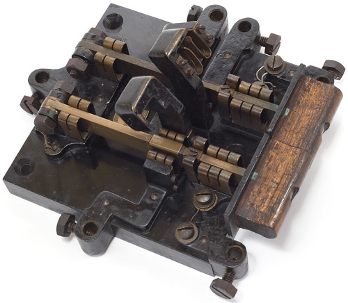
Knife switch - both blades up

This handsome object cost me $AU28.11 delivered, which I thought might have been a bit too much, until it arrived. I now realise I got a bargain. This thing's way cooler than I expected it to be.

All of the terminals and contacts work OK; a couple of the hefty terminal screws were seized and remain tight after cleaning and oiling, but this is a perfectly functional piece of gear.

The Bakelite-slab base is only about 14 centimetres square (5.5 inches), but the whole assembly weighs about 1.86 kilos (4.1 pounds). And it's surprisingly complicated.

Your standard two-blade knife switch is simple enough. It's either a dual-pole, single-throw, or a dual-pole, dual-throw (if you don't know what this means, check out the Wikipedia article on switches).

This thing, in comparison, is a freakin' logic puzzle.

It's got six terminals, and two separately hinged - but electrically connected - blades. The worn (and now lightly polished!) wooden handle is in two parts, too, one for each blade. But the two handle parts form a rebate joint.

Knife switch - one blade up

This makes it possible to have both blades down, both blades up, or only the left blade up. But, because of the rebate joint, you can't have the right blade up and not the left.

Knife switch - both blades down

Let's number the terminals clockwise from the one at the bottom right of this picture. So the one to its left is terminal 2, terminal 3 is the one on the back connected to the bases of the blades, and so on to number 6, which is partly obscured by the wooden handle in the above picture. Pay attention, there will be a test.

With both blades up, terminals 1, 2 and 6 are connected to nothing, and terminals 3, 4 and 5 are connected to each other.

With the right blade down and the left blade up, terminals 1, 2, 4 and 5 are disconnected, while 3 is connected to 6.

With both blades down, terminals 1, 3 and 6 are connected to each other, and terminals 2 and 4 are connected to each other; only terminal 5 is no longer connected to anything.

(If you can't quite see how that is the case, note that the middle section of the left blade, the lower one in the above picture, has a copper sleeve around it that's insulated from the blade itself. When that blade's down, the sleeve connects terminal 2 to terminal 4, but not to the blade itself.)

Oh, and terminals 1 and 6 are connected to the blade contacts via a couple of bits of might-perhaps-be-fuse-wire-but-probably-isn't. So you could easily connect either or both of them to some other part of the assembly, if you wanted.

(Does anybody know of a piece of software that'll take a description like this - "in state A, these parts are connected, in state B, the situation changes to this", et cetera - and will then draw you a diagram? I started drawing it out by hand in a flowcharting/circuit-diagram program, but then realised I had no idea how to draw these crazy ganged switches.)

The baseplate bears a little oval plaque that says:

VICTORIAN RAILWAYS
ELECTRICAL ENGINEERING BRANCH
WORKSHOP SPENCER ST.

(It just occurred to me that the switch could easily have been used for switching railway signals of some sort. The rebated handle interlock could be for something like preventing green lights for both directions on one line.)

I actually will use this switch as a switch, from time to time. But when it's not in use, I think I'll hang it on the wall somewhere.

Attack Of The Green Slime

A few months ago, I built myself a new server and from the outset it had that smell of new electronics breaking in. But the smell never went away. Not a burning smell, more like electrolytic caps. I'm always alert for scorching odour.

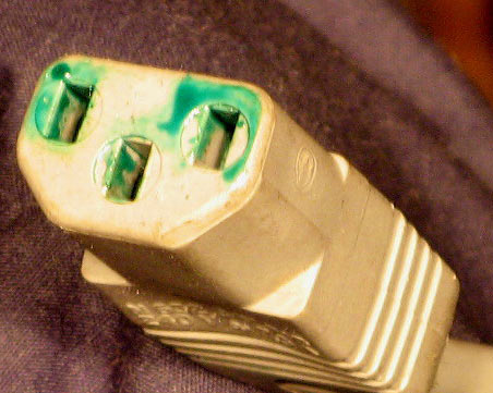
Today I needed to open up the system and unplugged its power cord and was surprised to find green slime on the contacts. Admittedly I mated a new power supply with a cord that is probably 10-15 years old.

It has a slight dimple on one face which makes the lettering appear curved in the photo.

IEC plug with strange green goop

Any idea what caused this?

Thanks,

Paul

The green-ness is a dead giveaway that this is one or more copper compounds, from corrosion of the contacts inside and/or the metal of the pins in the IEC socket.

Many copper compounds are green. The "verdigris" that makes the Statue of Liberty green, for instance, is primarily copper (II) carbonate. In the case of your goopy power plug, the wetness of the goop means that if the computer isn't sitting under a roof leak, there must be a hygroscopic (water-attracting) compound in there. That rules out copper carbonate, but there are several other copper compounds that'll suck water out of the air to one degree or another.

I think this process can be self-accelerating - a tiny bit of the hygroscopic compound is formed, it sucks up some water which dampens the area and accelerates the corrosion, and in the case of an electrical contact may further accelerate the reaction by increasing resistance so the area warms up. It's the warm copper compounds and/or plastic that's making the funny smell. It's also possible that outgassing from the plastic of the plug on the back of the new computer, or degeneration of the plastic in the old cord, has contributed to the reaction. Cable insulation is normally made from PVC, which stands for polyvinyl chloride, and every link in the PVC chain has a chlorine atom just waiting to be liberated, so I wouldn't be at all surprised if there was copper(II) chloride in the slime.

You can see similar green compounds discolouring the edges of copper or copper-alloy fittings in clothing, like riveted jeans or brass belt buckles. The copper compounds form a sticky goop there that's probably based on clothing fibres, sweat and shed skin flakes, all coloured (and flavoured!) by the copper compounds. (I presume hipsters who never wash their jeans develop particularly impressive rings of green goop.)

Fortunately, none of this is a big problem. Just discard the old IEC lead, make sure the pins inside the plug are clean (a pen eraser should be adequate to remove any tarnish), and plug in a new lead.